1. Vokatra mihoatraview
The Waveshare Industrial 8-Channel ESP32-S3 WiFi Relay Module is a high-performance control unit designed for industrial automation and IoT applications. It integrates an ESP32-S3 microcontroller, offering robust wireless communication capabilities (Wi-Fi and Bluetooth LE), multiple isolation protection circuits, and versatile connectivity options including isolated RS485 and an Ethernet port with optional Power over Ethernet (PoE).
This module features 8 high-quality relays and 8 digital inputs, making it suitable for controlling various devices and monitoring industrial signals. Its design emphasizes reliability and safety in demanding environments.
2. Endri-javatra fototra
- ESP32-S3 Microcontroller: Equipped with an Xtensa 32-bit LX7 dual-core processor, operating at up to 240 MHz for efficient processing.
- Fifandraisana tsy misy tariby: Integrated 2.4GHz Wi-Fi and Bluetooth LE dual-mode communication for flexible network integration.
- 8-Channel Relays: High-quality relays with a contact rating of ≤10A 250V AC / 30V DC, suitable for various loads.
- 8-Channel Digital Inputs: Supports both passive (dry contact) and active (wet contact) digital inputs with bi-directional optocoupler isolation.
- Isolated RS485 Interface: For reliable connection to Modbus industrial modules or sensors, featuring hardware automatic control and protection circuits (TVS diode, surge protection, ESD protection).
- Seranan-tsambo Ethernet: Onboard W5500 Ethernet chip for 10/100Mbps network communication.
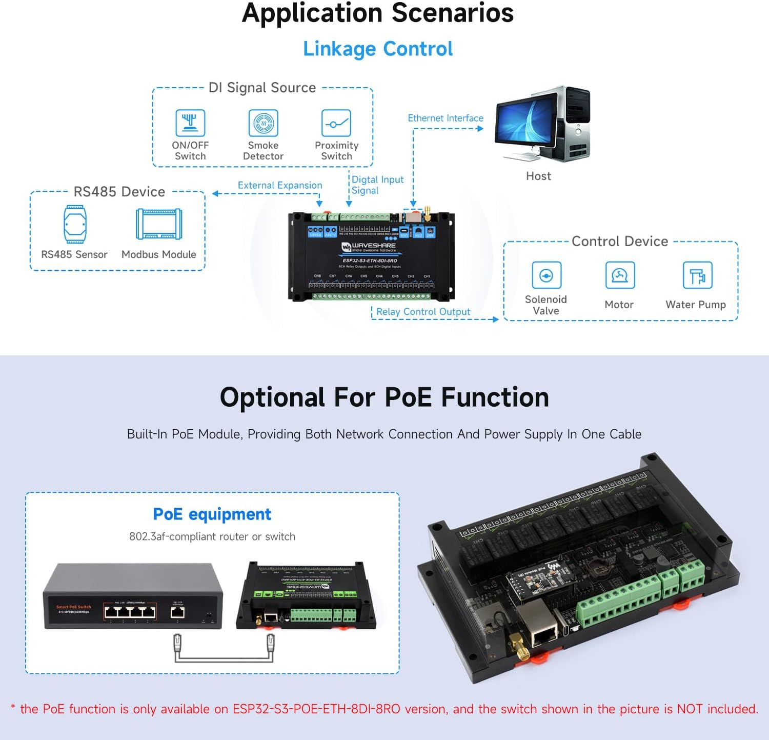
- Power over Ethernet (PoE): Optional version supports IEEE 802.3af standard for combined power and data over a single Ethernet cable.
- Fidirana herinaratra miovaova: Supports USB Type-C (5V) for power, debugging, and firmware, and a wide 7-36V DC screw terminal input for industrial applications.
- RTC Chip: Onboard Real-Time Clock for scheduled tasks and time-sensitive operations.
- Multiple Isolation Protection: Includes optocoupler isolation, power isolation, and digital isolation to prevent interference and ensure stable operation.
- Toetra famantarana: Built-in RGB LED, PWR, TXD, and RXD indicators for monitoring device status.
- Fefy: Rail-mounted ABS protective case for easy installation and enhanced safety.
3. Ny votoatin'ny fonosana
Hamarino tsara fa eo daholo ny entana rehetra ary ao anatin'ny toe-javatra tsara rehefa avy nosokafana ny fonosana.
- ESP32-S3-POE-ETH-8DI-8RO Module x 1
- 2.4G 4dBi SMA Antenna x 1
- Screwdriver x 1

4. Fametrahana sy fametrahana
4.1 Fifandraisana famatsiana herinaratra
The module supports multiple power input methods:
- USB Type-C: Connect a 5V USB power source to the USB Type-C port for power, debugging, and firmware uploading.
- Terminalan'ny Visy: Connect a 7-36V DC power supply to the designated screw terminals. Ensure correct polarity.
- Power over Ethernet (PoE): For the PoE version, connect an 802.3af compliant PoE switch or router to the Ethernet port. This provides both power and network connectivity through a single cable.
4.2 Fifandraisana amin'ny tambajotra
- Wifi: Attach the provided 2.4G SMA antenna to the external antenna connector. Configure Wi-Fi settings via firmware.
- Bluetooth LE: The module supports Bluetooth LE for short-range wireless communication.
- Ethernet: Connect a standard Ethernet cable to the RJ45 port for wired network access.
4.3 Fifandraisana Relay
The module provides 8 relay channels. Each relay has Normally Open (NO) and Common (COM) contacts. Refer to the diagram for wiring examples.
4.4 Digital Input Connections
The 8 digital inputs support both passive (dry contact) and active (wet contact) signals. Ensure proper wiring based on the sensor type.

4.5 RS485 Interface
Connect RS485 devices (e.g., Modbus modules, sensors) to the isolated RS485 screw terminals. The interface features hardware automatic control for data direction and includes protection circuits.
4.6 Enclosure and Mounting
The module is housed in a rail-mounted ABS protective case, designed for easy installation in industrial control cabinets using a 35mm DIN rail.
5. Torolàlana miasa
5.1 Fampandehanana sy Fandrindrana Voalohany
After connecting the power supply, the PWR LED should illuminate. The module can be configured via its Wi-Fi interface (AP mode), Ethernet, or through a serial connection via the USB Type-C port. Refer to the Waveshare Wiki for detailed programming and configuration guides.
5.2 Relay Control
The 8 relays can be controlled programmatically via the ESP32-S3 microcontroller. This allows for switching AC or DC loads based on logic defined in the firmware.
5.3 Digital Input Monitoring
Monitor the status of the 8 digital inputs to detect external events from sensors, switches, or other industrial signals. The bi-directional optocoupler isolation ensures signal integrity and protection.
5.4 RS485 Fifandraisana
Utilize the isolated RS485 interface for communication with other industrial devices, typically using the Modbus protocol. This enables data exchange and control within an industrial network.
5.5 Firmware Upload and Debugging
Connect the module to a computer via the USB Type-C port. Use the appropriate development environment (e.g., Arduino IDE, ESP-IDF) to upload custom firmware and debug applications.
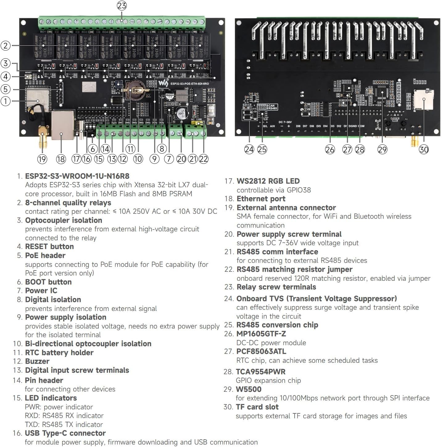
6. Fandrindrana ny birao sy ny singa
Understanding the board layout is crucial for proper connection and operation. The following diagrams highlight key components and their functions.
6.1 ambony View

- ESP32-S3-WROOM-1U-N16R8 (ESP32-S3 module)
- 8-channel quality relays
- Optocoupler isolation for relays
- bokotra RESET
- PoE header (for PoE module)
- bokotra BOOT
- Power IC
- Digital isolation
- Power supply isolation
- Bi-directional optocoupler isolation
- RTC mpihazona bateria
- Buzzer
- Digital input screw terminals
- Pin header (for other devices)
- LED indicators (PWR, RXD, TXD)
- USB Type-C connector
- WS2812 RGB LED
- seranan-tsambo Ethernet
- Mpampifandray antena ivelany
- Power supply screw terminal
- Fandraisana fifandraisana RS485
- RS485 matching resistor jumper
- Relay screw terminals
6.2 Ambany View
- Onboard TVS (Transient Voltage Suppressor)
- RS485 conversion chip
- MP1605GTF-Z (DC-DC power module)
- PCF85063ATL (RTC chip)
- TCA9554PWR (GPIO expansion chip)
- W5500 (Ethernet chip)
- TF karatra slot
7. Famaritana
| Sokajy | fikirana | sarobidy |
|---|---|---|
| Microcontroller | Module | ESP32-S3-WROOM-1U-N16R8 (ESP32-S3) |
| processeur | Xtensa 32-bit LX7 dual-core, up to 240 MHz | |
| Wireless Communication | Wifi | 2.4GHz (802.11 b/g/n) |
| Bluetooth | Bluetooth 5, BLE | |
| USB | Connector | USB Type-C |
| Herin'aratra | 5V | |
| Isolated Communication Interface | interface tsara | RS485 |
| MIARO | TVS diode, surge protection & ESD protection | |
| Ethernet Interface | Port | PoE Ethernet port (IEEE 802.3af standard for PoE version) |
| Fampidirana nomerika | Fantsona fampidirana | 8 |
| Fampidirana Voltage | 5V-36V | |
| Karazana fampidirana | Passive input / active input (NPN or PNP type) | |
| Karazana mitoka-monina | Bi-directional optocoupler isolation | |
| fampitàna | Relay Channels | 8 |
| Contact Rating | ≤10A 250V AC / 30V DC | |
| Contact Form | 1TSY 1NC | |
| Fitokana-monina | Optocoupler isolation | |
| LED famantarana | RGB | Programmable color LED |
| PWR | Tondro mena mahery | |
| TXD | Green TX indicator | |
| RXD | Blue RX indicator | |
| Power Supply Screw Terminal | BOKYtage Range | 7-36V |
| Bika Aman 'endrika | fefy | Rail-mount ABS protective case |
| lafiny | 175 × 90 × 40 (mm) |

8. Fikojakojana
The Waveshare Industrial 8-Channel ESP32-S3 WiFi Relay Module is designed for robust industrial use. To ensure its longevity and reliable operation:
- Fepetra ara-tontolo iainana: Operate the module within specified temperature and humidity ranges. Avoid exposure to excessive dust, moisture, or corrosive substances.
- Fanadiovana: Raha ilaina, diovy moramora amin'ny lamba malefaka sy maina ny ivelany amin'ny môdio. Aza mampiasa ranoka fanadiovana na solvent.
- Fanavaozana ny mikirao praogramanao: Regularly check the Waveshare Wiki for firmware updates to ensure optimal performance and access to new features.
- Fifandraisana: Periodically inspect all screw terminal connections to ensure they are secure and free from corrosion.
9. Famahana olana
If you encounter issues with your Waveshare Industrial 8-Channel ESP32-S3 WiFi Relay Module, consider the following troubleshooting steps:
- Tsy misy hery:
- Check if the power supply (USB-C or 7-36V terminal) is correctly connected and providing the specified voltage.
- Ensure the PWR LED is illuminated. If not, verify the power source.
- For PoE versions, confirm the Ethernet cable is connected to an active PoE switch/injector.
- No Network Connectivity (Wi-Fi/Ethernet):
- Wifi: Ensure the antenna is securely attached. Verify Wi-Fi credentials and network availability. Try resetting the module.
- Ethernet: Check the Ethernet cable connection. Confirm the network switch/router is operational.
- Relays Not Actuating:
- Verify the control logic in your firmware.
- Check the power supply to the module and the load connected to the relay.
- Ensure the load current and voltage do not exceed the relay's contact rating.
- Digital Inputs Not Responding:
- Confirm correct wiring for passive (dry contact) or active (wet contact) sensors.
- Check the sensor's functionality independently.
- Hamarino ny fampidirana voltage range for active inputs (5V-36V).
- RS485 Communication Issues:
- Check wiring polarity (A/B).
- Ensure the RS485 matching resistor jumper is correctly set if needed.
- Verify baud rate and communication parameters in your software.
For further assistance, consult the official Waveshare Wiki resources or contact Waveshare technical support.
10. Fanohanana sy loharanon-karena
Waveshare provides comprehensive resources to assist users with their products:
- Official Wiki: The Waveshare Wiki is the primary source for detailed documentation, programming guides, sample code, and technical specifications. Visit the Waveshare store page and look for the Wiki link.
- Tohana ara-teknika: For specific technical inquiries or issues not covered in the documentation, please contact Waveshare customer support through their official channels.
10.1 Fampahalalana momba ny fiantohana
Warranty terms and conditions for this product are provided by Waveshare. Please refer to the product packaging or the official Waveshare webtranokala ho an'ny fampahalalana momba ny fiantohana amin'ny antsipiriany.